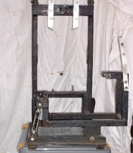
Engine and fan frame.
 The fan frame is a classic 'H' shape
made from 25mm square section steel tube. The
horizontal is much larger section recangle and is
drilled to take the 25mm spindle that the fan hub
spins on. This spindle has been welded into place.
The frame is fixed to the front of the duct at four points and it is also fixed to the floor.
Engine frame side view When I started building this frame, I was given a very sensible piece of advice which was to make sure that the fan frame can be removed from the craft without having to go underneath. This makes it much easier to get the frame out if it requires emergency repairs. With this point in mind, I fixed two pieces of angle iron to the floor and then bolted the fan frame to those so that it was easier to remove the frame.
Engine frame front viewThe engine is mounted in a cradle-like sub-frame that hangs the engine from its original mounts. It also carries the plumber block bearings.
This frame is bolted to the fan frame at a pivot on the right. The left hand side is supported by two turn-buckles so that I can quickly raise or lower the drive pulley to tension or change the drive belt.
Drive train
The drive is taken from the crankshaft through a flexible coupling, a couple of plumber block bearings to an 18 tooth H200 pully on a taperlock bush. A 410H200 drive belt takes the drive upto a 54 tooth pulley at the top. This is bolted to a hub which in turn, carries the fan.
Fan
I used 6 Multiwing 4Z blades in a 9 blade hub. Although this looks a little odd, it seems to work quite well.